
News


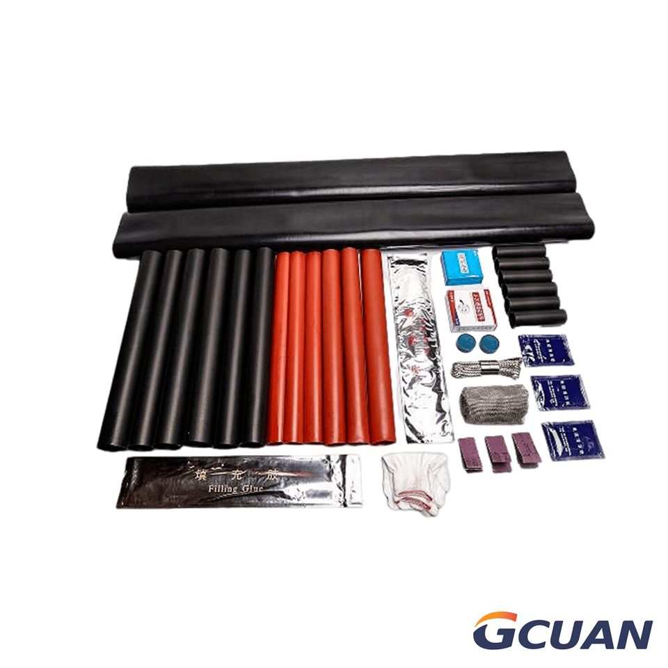
Installation of 8.7/15KV Heat Shrink Cable Joint
1. Preparatory Work a.The installation site should be free from dust, dry and ventilated. b.Check whether installation tools are complete. c.Check whether cable accessories match the cable correctly. d.Straighten and saw the two ends of the two cables to be connected evenly. 2. Stripping a.Strip off the outer sheath in sequence: 600mm for the long end and 400mm for the short end; leave 40mm of steel armor at both ends and strip off the rest, leave 40mm of inner sheath at both ends and strip off the rest; remove the filler (reserved for use) and separate the three phases. b.After measuring 220mm, strip off the copper shield and fix it with PVC tape. Keep 40mm of the semi-conductive layer and strip off the rest; be careful not to damage the insulation layer when stripping the semi-conductive layer. c.Polish the surface of the remaining steel armor and clean the outer sheath. d.Polish the outer sheath and inner sheath. e.Cut off the insulation layer according to 1/2 the length of the connecting pipe plus 5mm. Measure 35mm at the end of the insulation layer, cut it into a 30mm-long cone, and retain 5mm of the inner semi-conductive layer. 3. Fix Stress Pipe a.Cut the end of the outer semi-conductive layer into a cone shape. Polish the surface of the insulation layer with fine sandpaper, being careful not to polish the semi-conductive layer, remove residual semi-conductive particles, and clean the main insulation layer. b.Slide the stress tube over to overlap the outer semi-conductive layer by 20mm and heat it to shrink and fix. c.Slide the pipes and copper mesh in sequence, slide the protective sleeves onto both ends of the cable respectively; on the long end of the cable, slide one set of inner and outer red insulation tubes and inner and outer black semi-conductive tubes onto each phase respectively, and slide the copper mesh onto each phase of the short end of the cable respectively. 4. Install Connecting Pipe a.Slide the connecting pipe over and crimp it; when crimping, crimp from the middle of the connecting pipe to both ends. b.After crimping, file down the edges, corners and burrs on the connecting pipe and clean it. c.Wrap semi-conductive tape around the connecting pipe, overlapping 5mm of the inner semi-conductive layer on each side. d.Wrap filler tape and insulating self-adhesive tape on the semi-conductive tape to make a smooth transition between the connecting pipe and the main insulation, overlapping 10mm with the main insulation layer at both ends. 5. Install Heat Shrink Insulation Tube and Shielding Treatment a.Clean the outer surfaces of the insulation layer and the stress tube with cleaning paper. b.Place the three inner insulation tubes at the center of the connecting pipe, heat and shrink from the middle to both ends. Then place the three outer insulation tubes at the center of the inner insulation tubes, heat and shrink from the middle to both ends. c.Wrap sealant around the end face of the outer insulation tube from the copper shield port to fill the gap and wrap it into a cone shape. d.Place the semi-conductive tube at the center of the outer insulation tube, heat and shrink. Wrap semi-conductive tape around the overlapping area between the copper shield and the semi-conductive tube for 5mm. e.Stretch the copper mesh to cover the semi-conductive tube, overlap both ends on the cable's copper shield, and fix it with insulating tape. 6. Sealing Treatment a.Arrange the three phases together, restore the filler, and fix it with PVC tape. b.Connect the steel armor at both ends of the cable with a grounding wire and fix it with a constant force spring. c.Fix the constant force spring with PVC tape and wrap filler tape around the constant force spring and the outer sheath to fill the gap. d.Wrap sealant 30mm from the outer sheath and inner sheath at both ends of the cable. e.Clean the sheaths at both ends and preheat them. Pull the protective sleeve from the long end, place it on the sealant and heat it to shrink until a small amount of hot melt adhesive oozes out; clean the right end of the shrunk protective sleeve, pull the protective sleeve from the short end, overlap it with the shrunk protective sleeve, and treat it the same as the long end. Wrap self-adhesive tape around the overlapping parts at both ends and the middle of the protective sleeves to enhance sealing. f.After the joint installation is completed and fully cooled, clean the surface carbon black with a cleaning agent and start testing and operatio
4/15, 2026
read more
The Most Overlooked Interface in Power Systems — And How to Get It Right
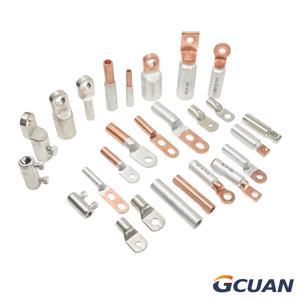
In power systems, discussions often focus on generators, transformers, and protection devices.Yet many reliability issues originate at a much smaller interface: the cable lug. A cable lug is where electrical power leaves the conductor and enters the system.Every megawatt delivered passes through this single connection point. Because it is small and looks simple, it is often treated as a standard accessory.In reality, it is a critical engineered interface—and one that requires the right solution. | Small interface. System-level impact. The real problem is not the lug — it’s the interface Cable lugs rarely fail suddenly. Most problems develop gradually and show early signs such as: • Slight temperature rise • Subtle discoloration • Unusual odor without visible smoke • Protection trips with no clear electrical fault These symptoms indicate increased contact resistance and mechanical degradation at the interface. | Most failures start quietly—long before alarms appear. Why failures keep repeating Many cable lug issues are incorrectly labeled as “electrical failures.”In practice, they are usually caused by mechanical and installation-related factors: • Lug material not matched to conductor or environment • Incorrect crimping method or die selection • Poor surface preparation • Incorrect tightening torque • Loosening caused by thermal cycling over time Electric current only exposes these weaknesses—it does not create them. | Electricity reveals weakness. It doesn’t cause it. A solution-oriented engineering approach Improving cable lug reliability does not require complex technology.It requires treating the lug as part of the system design, not an afterthought. Effective solutions focus on: • Correct material selection based on conductor type and operating conditions • Controlled crimping processes using appropriate tools and dies • Defined installation torque to achieve stable contact pressure • Interface cleanliness and surface preparation • Periodic inspection and re-torque in critical applications These measures significantly reduce heat buildup, resistance increase, and long-term degradation. | Reliability is designed, not assumed. Designing reliability at the connection point Experienced engineers evaluate more than current ratings: • How the lug is installed, not just its datasheet value • Contact pressure stability, not only cable size • Heat distribution trends, not only protection events Reliability is built at the interface, not on drawings. | The drawing ends where real reliability begins. From component thinking to system thinking Cable lugs do not generate power.But they decide whether power is transferred efficiently—or lost as heat. In power systems, the smallest components often determine overall reliability.By treating cable lugs as engineered interfaces and applying a solution-driven approach, operators can prevent unplanned shutdowns, reduce fire risk, and extend asset life. | Treat cable lugs as interfaces, not accessories.
1/6, 2026
read more
New Equipment Arrives at Our New Factory
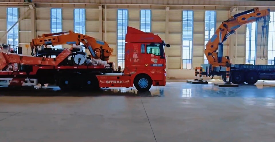
New Equipment Arrives at Our New Factory, Marking a Key Step in Production Capacity Upgrade. We are pleased to announce a major step forward in the development of our new factory: the first batch of core manufacturing equipment has recently arrived and entered the installation phase. The successful installation of this equipment marks a critical phase in the operational launch of the new facility. As more equipment is installed and commissioned, we will rapidly enhance our mass production capabilities, enabling us to deliver more efficient and consistent products and services to our customers. We look forward to the full operation of our new factory and to continuing to create value for you.
10/29, 2025
read more
What Are Cable Lugs?
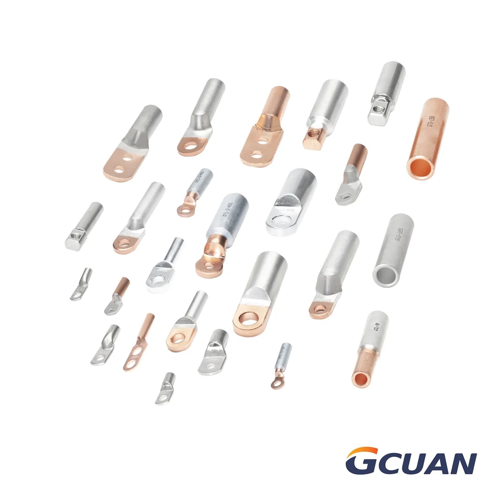
I. IntroductionHave you ever noticed the metallic luster at the end of your cables or between the wires? That’s a cable lug. Cable lugs are components used to connect cables to electrical devices, machinery, distribution cabinets, or other transmission lines. Designed for easy installation and removal, cable lugs are ideal for situations where permanent, fixed connections are unnecessary or impractical, making them a convenient choice for repairs and maintenance.II. Types and Materials of Cable LugsCable lugs come in various shapes and sizes, each tailored for different types of electrical connections. Typically made from copper, aluminum, or other conductive materials, they are designed to ensure a secure and reliable connection, minimizing the risk of electrical faults or power loss.• Copper Lugs: Copper is preferred in many applications due to its low resistance and excellent conductivity. It is commonly used in high-performance systems.• Aluminum Lugs: Lighter and more cost-effective, aluminum lugs are often used for large-scale installations like power plants, where weight and cost are critical factors.• Tin-Plated Copper Lugs: For enhanced corrosion resistance, especially in harsh environments like outdoor installations or marine applications, tin-plated copper lugs are often used.III. Applications of Cable LugsCable lugs are used in a variety of industries and applications, including:• Transportation: For cable fixing in rail transit and other fields.• Industrial: In heavy machinery and power systems, where reliable and robust connections are critical.• Marine: For electrical connections on boats or ships, where corrosion resistance is particularly important due to the salty environment.• Electrical Grids and Power Stations: For connecting cables in high-voltage transmission and distribution systems.IV. Where to Buy Cable Lugs?Guchuan (Shanghai) Import and Export Co., Ltd., a subsidiary of Guchuan Technology Holdings Limited, specializes in providing high-quality electrical products. Based in Shanghai, Guchuan offers reliable and innovative solutions for the global power industry.Our product range includes:• Cable Lugs and Connectors• Overhead Power Line Connectors• Heat and Cold Shrinkable Cable Accessories• Power Distribution Terminals• DIN Rail & Accessories• Pin Type BusbarsGuchuan's products are designed to meet international standards and are used across a variety of industries, ensuring safe, efficient, and reliable connections for electrical systems. They focus on quality, performance, and long-term durability, providing solutions for applications in power transmission, renewable energy, and more.To explore our full range of products and learn more about our solutions, please visit Guchuan Website.
8/26, 2025
read more
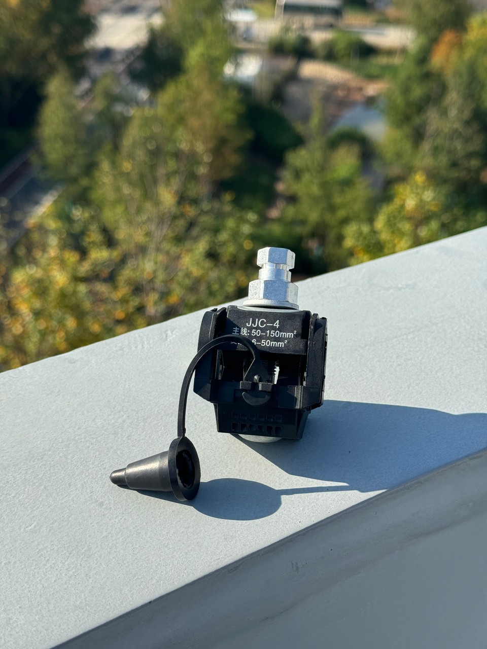
How to Install Insulated Piercing Connectors
Insulated Piercing Connectors (IPCs) are commonly used in electrical installations to tap into existing insulated conductors without stripping the wire. They provide a secure, weatherproof connection and are widely used in overhead power lines, street lighting, and renewable energy systems. Tools and Materials Required - Insulated Piercing Connector (appropriate size for the cable) - Cable cutter/stripper (if needed) - Torque wrench or hex key (depending on connector type) - Insulation-piercing connector tool (if required) - Safety gloves & glasses - Voltage tester (for live line applications) Step-by-Step Installation Guide 1. Power Off (If Possible)- For safety, de-energize the circuit before installation. If working on live lines, follow proper electrical safety protocols. 2. Select the Correct Connector - Ensure the IPC matches the cable size and insulation type. Check manufacturer specifications for compatibility. 3. Position the Connector- Place the connector over the main cable where the tap will be made. Align the piercing teeth with the conductor. 4. Tighten the Connector- Use a torque wrench or hex key to tighten the connector bolts evenly. - Follow the manufacturer’s recommended torque value to ensure a proper seal without damaging the cable. 5. Insert the Tap Cable (If Applicable)- If the IPC has a tap port, insert the secondary cable and secure it according to the connector’s design. 6. Check the Connection- Ensure the connector is fully seated and insulated. - For live installations, use a voltage tester to confirm a secure connection. Safety Tips - Always wear insulated gloves when working near live wires. - Avoid over-tightening, which can damage the conductor. - Use weatherproof IPCs for outdoor applications. By following these steps, you can ensure a reliable and safe electrical connection using Insulated Piercing Connectors.
5/29, 2025
read more
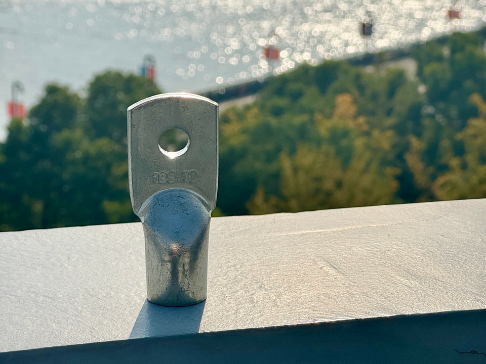
How to install cable clamps?
Installing cable clamps is a fundamental task in electrical and mechanical projects. To install cable clamps, you need to prepare the appropriate tools and materials. During installation, mark the location, prepare the surface, fix the base, insert the cable and clamp it in a suitable way, and finally check and test. Here's a comprehensive guide on how to install cable clamps effectively.
5/5, 2025
read more